
-
×
 ANjo EFW80C10 EndFed 5-Band Wire Antenna
1 × 213.00 €
ANjo EFW80C10 EndFed 5-Band Wire Antenna
1 × 213.00 €
Subtotal: 213.00 €
In stock
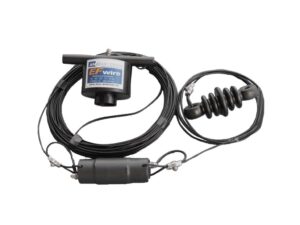
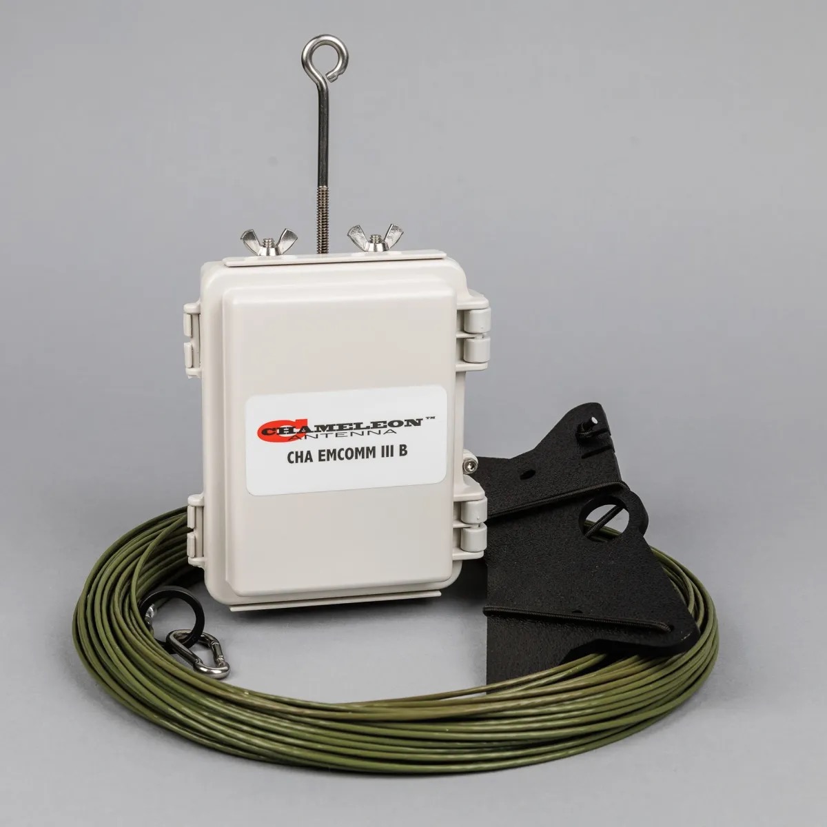
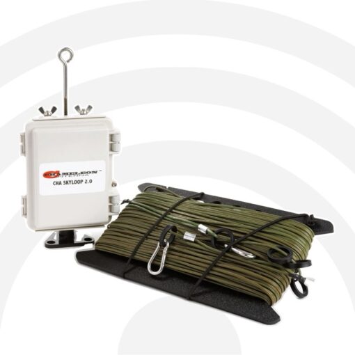
The Chameleon EMCOMM III BASE is an effective multi-band High Frequency (HF) antenna specially designed for short to long range base station HF communications.
225.00 €
In stock
Due to configuration and installation flexibility and low visibility design, Chameleon EMCOMM III BASE is ideal for home use even in developments with antenna restrictions. It is also highly suitable for military, government agencies, non-governmental organizations (NGOs), Military Affiliate Radio System (MARS), Civil Air Patrol (CAP), Amateur Radio Emergency Service (ARES) / Radio Amateur Civil Emergency Service (RACES), Salvation Army Team Emergency Radio Network (SATERN), and shortwave listening.
The EMCOMM III Base antenna is configurable to facilitate both long distance (DX) and Near-Vertical Incident Sky wave (NVIS) communication and using an automatic antenna tuner or coupler with memory settings will support most Automatic Link Establishment (ALE), frequency-hopping, and spread- spectrum modes and operations.
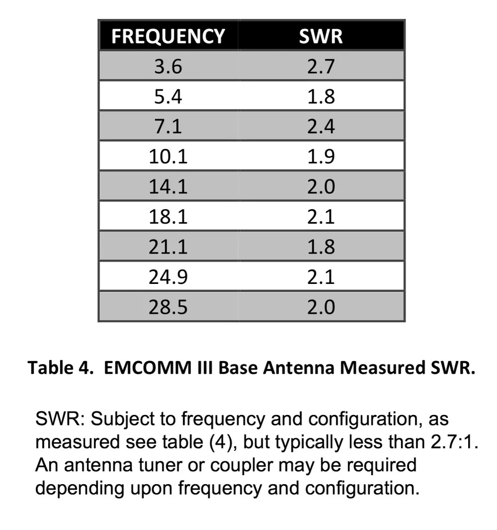
SWR: Subject to frequency and configuration, but typically less than 2.7:1. An antenna tuner or coupler may be required depending upon frequency and configuration.
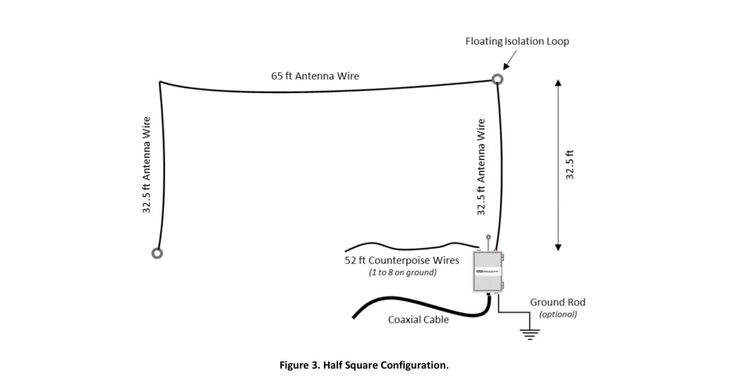
The EMCOMM III Base antenna can be installed by the operator in less than 30 minutes. It should be installed as high and straight as possible, but almost any available supports, such as an existing antenna tower, trees, a flag pole, the eaves of a house, or a non-conductive fence can be used with satisfactory results.
The EMCOMM III Base antenna is comprised of a matching transformer and a 40 meter antenna wire on a line winder – making an effective HF base station antenna system for permanent installation as a primary or backup HF base station antenna.
Specifications:
Frequency: 10M – 160M
Power: 500W SSB or 250W CW
Length: 40m Tinned Copper KEVLAR PTFE (Teflon) (-70°C to 150°C) wire
Weight: 1.0 kg.
The antenna system consists of:
1 X CHA EMCOMM III matching box
1 X 40m Tinned Copper KEVLAR PTFE (Teflon) (-70°C to 150°C) wire
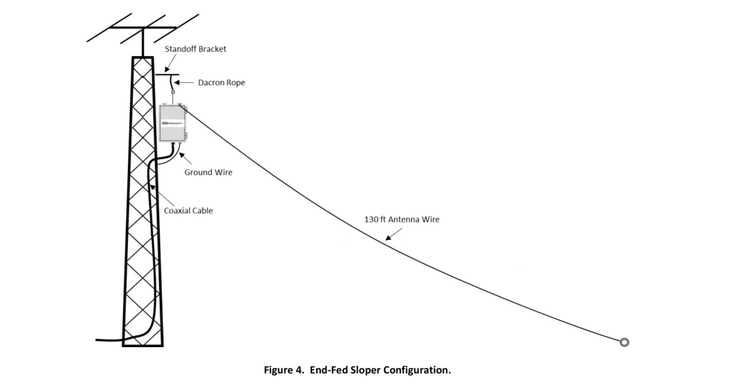
Sloper Installation
The sloper is considered the most unusual antenna system and can be difficult to get to work properly. The sloper may exhibit some gain in one direction, but usually has omni direction pattern. There are two types of sloper, the full sloper, really a dipole mounted with one end higher than the other. The half-sloper (EMCOMM III BASE) is fed at one end with a “ground system” or counter poise provided by either physical ground if fed at lower end of sloper. If the sloper is fed at the top, then other factors provide the “ground”. In most cases, a sloper mounted on a tower, then the tower and importantly, the beam mounted on top, act as the counterpoise.
One successful version of the sloper (most folks call any kind of sloper simply a “sloper” regardless of its type) is one that is fed with coax. The antenna is fed from the top and installed on a tower with a beam on top. The center conductor of the coax feeds the sloper wire and the shield is carefully bonded to the tower structure. In addition the beam, rotor, and mast are electrically bonded to the tower (here a heavy braided strap connecting the mast to the tower is recommended). The theory is that the sloper is fed at the top and the high current point is high just under the beam, leading away from the tower.
The sloper has been reported to be hard to get to work in some cases. When it works, its performance when used with a tower and a beam is very good. Considering the cost of materials (assuming the tower is in place already) the sloper should be considered.
Inverted “L” Installation
This is most likely the least expensive high performance antenna you can erect for 40M, 80M and 160M (limited performance). It is worth investigating since it needs only one high point in the relative clear to be effective (the horizontal far end can be at a lesser elevation, details later). Most likely you will need to use an external antenna tuner.
The main radiating component of the “L” is the vertical wire, that’s what makes it a very good ground-wave and DX antenna. So it would be good if this can be kept in the clear, or several feet away from your tower, and of course, as high as you can make it. The horizontal part may slope downward, or bent several times to accommodate any obstacles. Keep in mind, the more you bend the element back on itself, the more of the radiated signal is canceled out.
Sometimes it is not possible to have the vertical section longer than the horizontal section. This will result in more of the signal being radiated skyward to which NVIS (Near Vertical Incident Skywave) will occur. NVIS is a propagation method that provides usable signals in the range between ground wave and skywave distances (usually 50 to 650 km).
Before we go any further, this antenna requires a robust ground system. If your ground is poor, the antenna efficiency will be poor, and you will be troubled with RF in the shack.
The radiation pattern is omni directional, with a possible minor lobe in the direction of the horizontal portion.
You must be logged in to post a review.

There are no reviews yet.